

Building the FGC-9
- Wes Gardner
- Feb 26, 2024
- 8 min read
Updated: Jan 31, 2025

Since the FGC-9 was introduced, the ability to build one has become ever more streamlined and 3D printing techniques have evolved to allow for tougher prints and integrated fasteners. We are going to walk through an FGC-9 build with a couple of upgrades that show how the base design can be improved upon while at the same time simplifying the build process for the average person.
This article is not designed to replace the original build guide, but is instead to be used as a supplemental resource showcasing some alternate parts or build techniques that we believe enhances the overall design. Before attempting this type of build you should already be familiar with your 3D printer and have a good understanding of the necessary tuning to ensure you get dimensionally accurate and sound prints.
The original build guide shows the orientation in which the individual parts should be printed and we are not going to deviate from that here. All parts were printed in PLA+ using a "99 perimeter" infill style and "build plate only" tree supports. Many of the original designed parts are utilized, however, the following parts have been modified and will be shown in this build guide:
Upper Receiver
Hex nut sockets have been added for the handguard and buffer tube screws. This is done with filament changes at the appropriate layers so the nuts can be added and then printed over afterwards.
A picatinny rail was integrated into the receiver to eliminate the extra screws and printed rail parts in the original design.
Lower Receiver
Hex nut sockets for the takedown screws have been added for a more streamlined fitment. This includes shortening the rear takedown screw as well.
The lower receiver has been modified for thumb clearance over the safety selector as it was found that the original design didn't leave much room to manipulate the selector from "SAFE" to "FIRE".
Through hole added for the magazine catch pivot pin should the pin need to be removed in the future. This was done after having the printed pivot pin fail in the past. This also allows for the use of a metal pin if the end user so chose.
1/4-28 TPI threads printed into the lower for an AR-15 grip screw. This allows the builder to use more parts from a purchased AR-15 lower parts kit.
Magazine catch
Remixed design for aesthetics only.
Pistol Brace
The stock in the build guide was swapped for a FGC-9 pistol brace for legality reasons.
Getting Started
Before we start with the lower receiver and trigger group we need to ream the selector hole using a 3/8" reamer (a 3/8" drill bit could be used in a pinch).


Now we can gather the AR-15 fire control group and lay it out. First we will install the AR-15 trigger, disconnector and associated springs into the lower receiver using the original AR trigger pin.


We then install the AR-15 hammer and spring with a longer hammer pin as per the build guide as the original hammer pin isn't quite long enough for the FGC-9's design. The legs of the hammer spring fit into the notches on top of the trigger pin to help secure the trigger pin in the receiver.


Now we can install the safety selector, detent and spring. The selector should be lightly oiled prior to installation to allow it to rotate freely. Install the selector detent into the receiver and spring into the grip. The grip is installed using the 1/4-28 screw and external tooth washer while making sure that you don't overtighten the screw and crack the lower, snug is plenty and the washer will keep it from loosening up.


Once the grip is installed the trigger group is function checked to ensure the safety and disconnector work. Make sure to capture the hammer with your thumb to keep the hammer from hitting the front edge of the fire control pocket of the lower when doing this check. You also want to check to ensure the disconnector will catch the hammer during reset as well. Things work as expected when using a high quality fire control group and this is no area to save money.


Now we can install the magazine catch assembly and feed ramp. We use the magazine catch spring from an AR-15 along with a 3D printed retaining pin (optionally you can use the same material as the hammer pin to hold in the mag catch). The magazine release also uses an ambidextrous release button that is 3D printed as well. The feed ramp is held in with a 12mm long M3 Socket Head Cap Screw (SHCS).


After the feed ramp and magazine catch are installed we can test the magazine's fit and clearance with the feed ramp and ensure the mag falls freely when the release is pressed.

Next we will prep the buffer tube and brace. The buffer tube screw hole will need to be tapped using an M4 tap in preparation for the 30mm long M4 screw. The buffer system for the FGC-9 utilizes a dual spring setup of a primary spring (AR-15 Carbine buffer spring) and a smaller stiffer secondary spring seated into the bottom of the buffer tube. The support from the inside of the buffer tube can be used as a "pusher" tool to help seat the secondary spring into the recess in the back of the buffer tube.


The ejector is held into the upper receiver with a single 16mm M3 screw. Make sure the isn't any support material left in the screw hole and ensure you don't use any screw longer than 16mm or you will damage the upper receiver.


Now we will work on the bolt shroud and charging handle. The charging handle is made up of 3 pieces (2x 3D printed parts and a 5mm allen key) that are epoxied together. I used Marine-tex brand of epoxy as I find it easy to mix and work with and it hardens up very well. We will also install the firing pin retaining screw (20mm long M3 screw) at this point and epoxy over the nut to ensure it doesn't come loose during firing (if it does it will chew up the inside of the upper receiver.


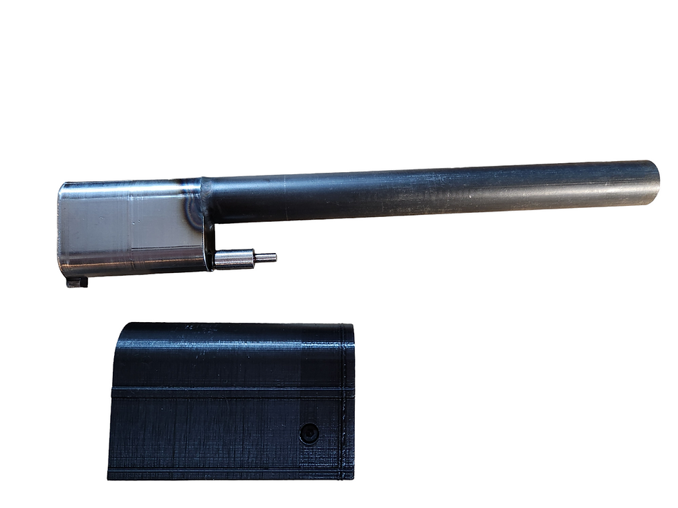
Two of the items that make the build go much easier and quickly are a prefabricated bolt kit and barrel. Our CNC bolt kit drops into the factory bolt shroud and eliminates the need for any drilling or welding to produce the FGC-9's bolt. The bolt kit also does NOT need to be epoxied in place and allows for the bolt to be removed and used in another build. The firing pin protrusion is also set in this new design so no grinding of the return spring is needed.


The bolt kit slides directly into the bolt shroud until the feel lip on the bolt stops against the cutout on the bottom of the shroud.

The barrel is set into the upper receiver until the barrel face meets the shelf in the upper receiver. The charging handle is then installed in the upper receiver and the handguard/barrel retainer is installed with 4x 40mm M3 screws. The 3mm hex nuts shown below are what are used inside the upper receiver and for the lower receiver's takedown bolts.


This shows the nut pockets that are set into the upper receiver during printing.


The ejector needs to be in the "ejected" position before the bolt is installed into the upper receiver.


The rear takedown screw in our build will need to be shortened down to ~33.6mm in length to allow for a flush fit on the lower receiver while the front takedown screw can be left at the 40mm length.


The lower can now be installed into the upper receiver keeping in mind that the feed ramp's notch needs to slip into the upper receiver. The lower is slid forward until the takedown holes line up.


Once the lower is assembled into the upper, the buttstock can now be installed. The main buffer spring is slid over the bolt tail and the buttstock secured with 3x 30mm M3 screws. The original design utilized a 4th screw into the lower receiver but I have found this additional screw to be unnecessary with the embedded nuts and omitting it means we don't have to mess with any heat-press brass inserts further simplifying the build.

Now we have our very own FGC-9 ready to hit the range and enjoy.


READY GOOD INFO HOMIE
Where did you find the files for the brace? It looks great, but I can't find one like it anywhere!